Machines made by CITIZEN

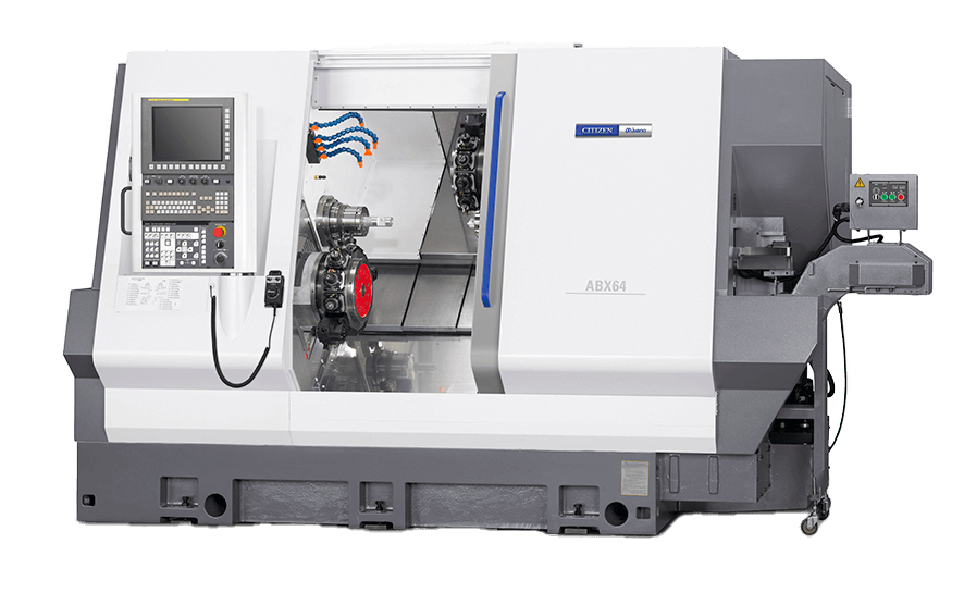
ABX-51/64
THY2 (3-Turret) | SYY2 (2-Turret)
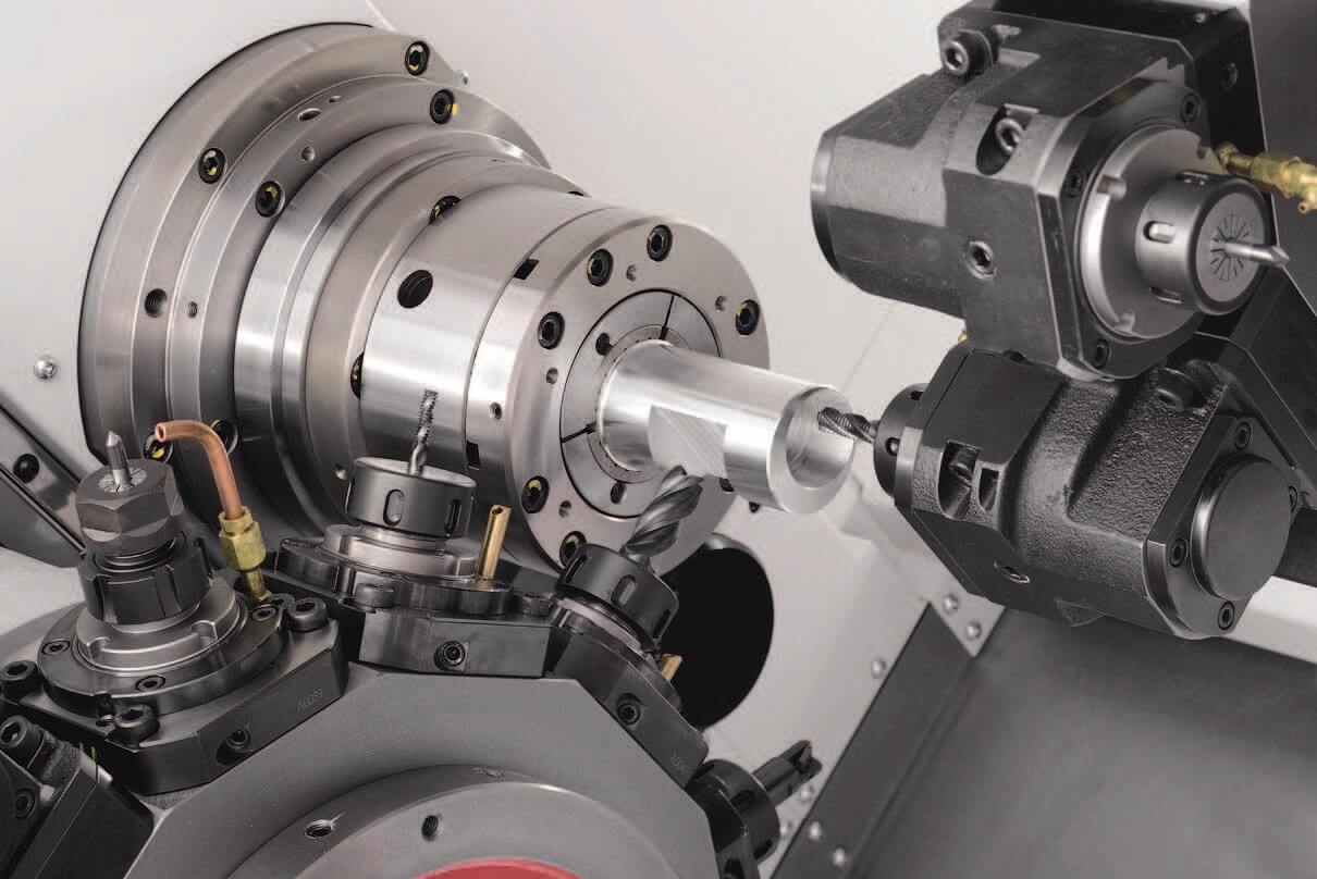
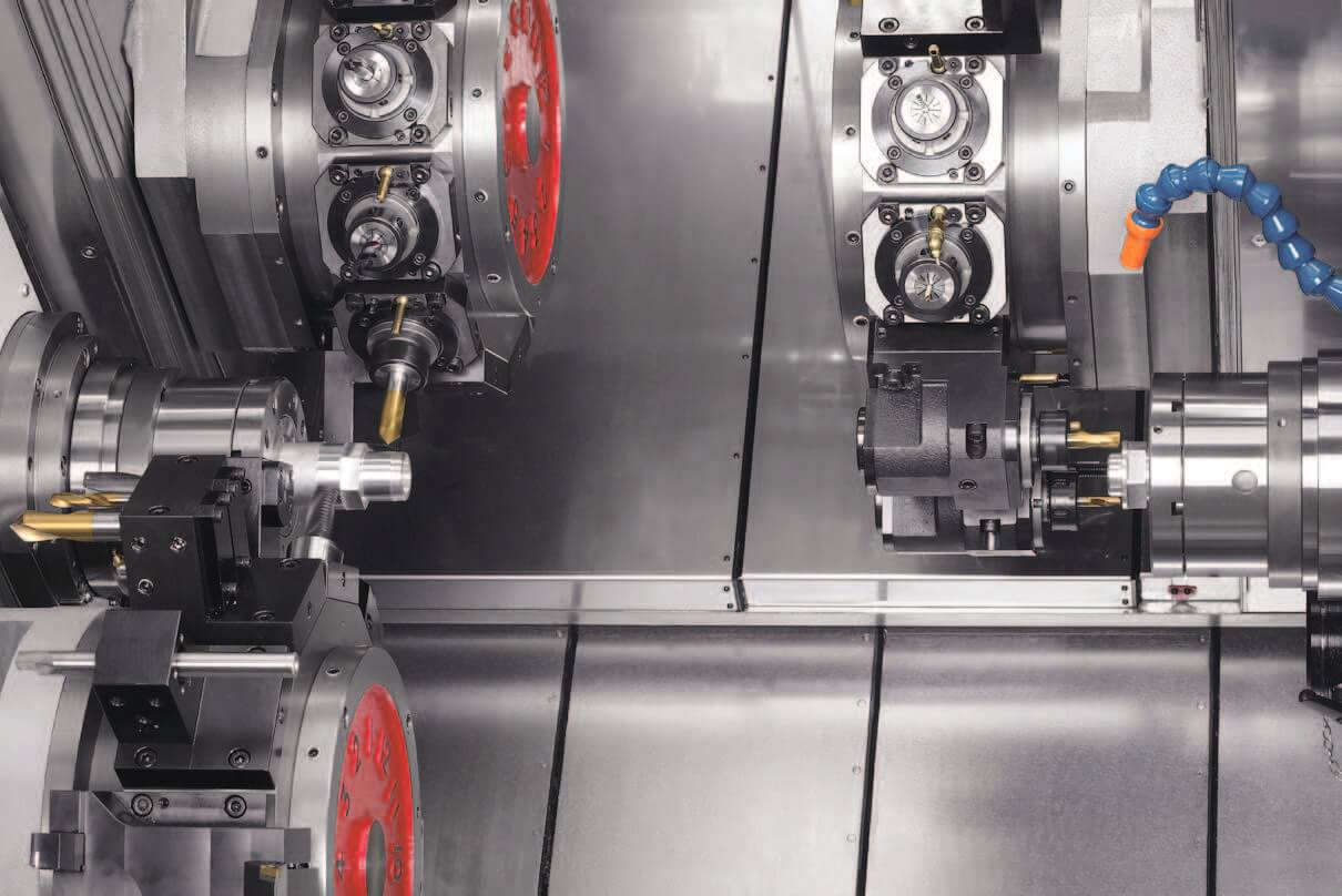
The perfect turning center featuring up to three Y-axes for extreme efficiency. Equipped with 40 Nm high-torque revolving tools for complex milling operations.
51mm / 64mm Bar Capacity
2 or 3 Turrets with Y-Axis
40 Nm Revolving Tool Torque
| Item | ABX-51THY2 | ABX-64THY2 | ABX-51SYY2 | ABX-64SYY2 |
|---|---|---|---|---|
| Machining Capacity | ||||
| Max. work length SP1 | 125 mm | 118 mm | 125 mm | 118 mm |
| Max. work length SP2 | 125 mm | |||
| Max. bar diameter SP1 | 51 mm | 64 mm | 51 mm | 64 mm |
| Max. bar diameter SP2 | 51 mm | |||
| Max. power chuck diameter SP1 | 165 mm | -- | 165 mm | -- |
| Max. power chuck diameter SP2 | 165 mm | |||
| Spindle Data | ||||
| Spindle speed SP1 | 5,000 min⁻¹ | 4,000 min⁻¹ | 5,000 min⁻¹ | 4,000 min⁻¹ |
| Spindle speed SP2 | 5,000 min⁻¹ | |||
| Inner dia. of draw tube SP1 | 52 mm | 65.5 mm | 52 mm | 65.5 mm |
| Inner dia. of draw tube SP2 | ∅ 52 mm | |||
| Chucking system SP1, SP2 | Hydraulic cylinder | |||
| Collet Chuck Type SP1 | H-S22/177E | H-S26/185E | H-S22/177E | H-S26/185E |
| Collet Chuck Type SP2 | H-S22 / DIN177E | |||
| Turret & Tooling | ||||
| Number of turrets | 3 | 3 | 2 | 2 |
| Tool shank size (Sq) | 20 mm Sq. | |||
| I.D. tool hole size | 25 mm / 40 mm Dia. | |||
| Index time (HD1, 2, 3) | 0.25 SEC / 1 POS | |||
| Revolving tools (Max) | 36 | 36 | 24 | 24 |
| Max Revolving Speed | 6,000 min⁻¹ | |||
| Drilling / Tapping capacity | Max ∅ 20 / Max M14x2 | |||
| Rapid Traverse Rates (m/min) | ||||
| HD1 / HD2 (X / Z / Y) | 16 / 20 / 12 | 16 / 20 / 12 | 16 / 30 / 12 | 16 / 30 / 12 |
| HD3 (X3 / Z3 / Y3) | 16 / 20 / 12 | 16 / 20 / 12 | -- | -- |
| SP2 Zs (Sub Spindle) | 30 m / min | |||
| Physical / Electrical / Tanks | ||||
| Spindle Motor SP1 | AC 15 / 11 kW | |||
| Spindle Motor SP2 | AC 7.5 / 5.5 kW | |||
| Revolving Tool Motor | AC 4.5 kW | |||
| Coolant Tank Capacity | 400 L | |||
| Hydraulic / Lube Tank | 10 L / 4 L | |||
| Floor Space | 3,290 × 2,204 mm | |||
| Machine Weight | 11,350 kg | 10,900 kg | ||
| Power Capacity / Fuse | 49 KVA / 150A | 49 KVA / 150A | 48 KVA / 150A | 48 KVA / 150A |
| Air Supply | 0.5 MPa (5 kgf / cm²) | |||
ABX-THY2 (3-System)
- HD1: X1,Z1,Y1,C1,A1,E1 | HD2: X2,Z2,Y2,C2,A2,E2 | HD3: X3,Z3,Y3,C3,A3,E3
- Storage: 128 KB (320 m) / 250 Programs
- 96 Tool Offset Pairs
ABX-SYY2 (2-System)
- HD1: X1,Z1,Y1,C1,A1,E1 | HD2: X2,Z2,Y2,C2,A2,E2
- Storage: 64 KB (160 m) / 125 Programs
- 64 Tool Offset Pairs
Common Advanced Functions:
Cs outline control, Polar coordinate interpolation, Synchronization/Mixture control, 10.4" color LCD, absolute position detection, and Custom Macro.
Standard Accessories
- High pressure coolant & Parts catcher (Servo)
- Revolving tools & Driving unit
- Thermo revision & Splash guard interlock
- Pneumatic & Spindle brake
Optional Equipment
- Chip conveyor & Tool setter
- Bar feeder interface & Spindle inner bushing
- Work ejector No.2 & Drill breakage detector
- 6" Power chuck system
GALLERY & MEDIA
Watch ABX Demo